
Emission Characteristics of Radio Transmissions
Sun 22nd February 2009 19:10
•
Between 0.001 and 999 Hz shall be expressed in Hz (letter H);
•
Between 1.00 and 999 kHz shall be expressed in kHz (letter K);
•
Between 1.00 and 999 MHz shall be expressed in MHz (letter M);
•
Between 1.00 and 999 GHz shall be expressed in GHz (letter G).
Background
The International Code for Radio Emission Modes method came into use on a worldwide basis on 1 January 1982. It is used to describe every type of Radio Transmission.
The International Code for Radio Emission Modes method came into use on a worldwide basis on 1 January 1982. It is used to describe every type of Radio Transmission.
INTERNATIONAL CODE FOR RADIO EMISSION MODES
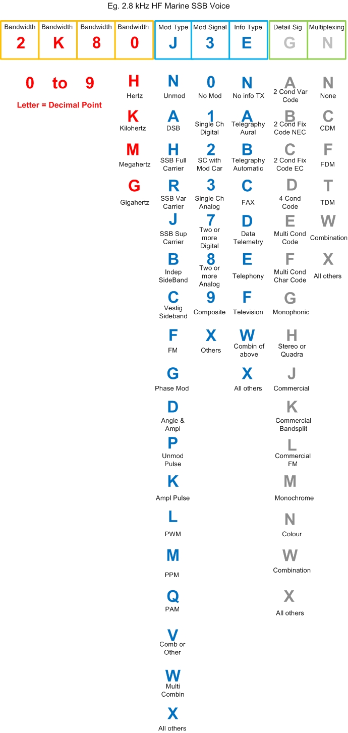
The full designation of emissions comprises a total of nine alphanumeric symbols, with the first seven being mandatory and most often used.
These nine symbols are divided in the ratio 4 : 3 : 2.
The first four symbols provide details of the necessary bandwidth which can range from 0.001 Hz to 999 GHz.
The next three symbols provide details of the basic characteristics of the emission.
The last two symbols, which are optional, describe any additional characteristics which may be useful in providing a more complete description of the emission.
The First Four Symbols
The first four symbols provide details of the necessary bandwidth which is defined as: For a given class of emission, the width of the frequency band which is just sufficient to ensure the transmission of information at the rate and with the quality required under specified conditions.
The necessary bandwidth shall be expressed by three numerals and one letter. The letter occupies the position of the decimal point; it represents the Unit of Bandwidth and may be H for Hertz, K for kilohertz, M for Megahertz or G for Gigahertz.
In order to avoid a given bandwidth being expressed in more than one way, depending upon the choice of the unit, it is specified that the first character shall be neither zero nor K, M, or G.
It is further specified that the necessary bandwidth:
The Next Three Symbols
These symbols describe the basic characteristics of the radio emission:
1. First symbol defines type of modulation of the main carrier;
2. Second symbol defines nature of signal(s) modulating the main carrier;
3. Third symbol defines type of information to be transmitted.
It is not possible to give the minimum required information on the emission without the use of all three symbols.
1. First Symbol - type of modulation of the main carrier
(a) Emission of an unmodulated carrier N
(b) Emission in which the main carrier is amplitude modulated (including cases where sub-carriers are angle modulated)
(i) Double sideband A
(ii) Single sideband, full carrier H
(iii) Single sideband, reduced or variable level carrier R
(iv) Single sideband, suppressed carrier J
(v) Independent sideband B
(vi) Vestigial sideband C
(c) Emission in which the main carrier is angle modulated
(i) Frequency modulation F
(ii) Phase modulation G
(d) Emission in which the main carrier is amplitude and angle modulated either simultaneously or in a pre-established sequence D
(e) Emission of pulses (1)
(i) Unmodulated sequence of pulses P
(ii) A sequence of pulses -
(1) modulated in amplitude K
(2) modulated in width/duration L
(3) modulated in position/phase M
(4) in which the carrier is angle modulated during the period of the pulse Q
(5) which is a combination of the foregoing or is produced by other means V
(f) Cases not covered above, in which an emission consists of the main carrier modulated, either simultaneously or in a pre-established sequence, in a combination of two or more of the following modes; amplitude, angle, pulse W
(g) Cases not otherwise covered X
2. Second Symbol - nature of signal(s) modulating the main carrier
(a) No modulating signal 0
(b) A single channel containing quantized or digital information without the use of a modulating sub-carrier (2) 1
(c) A single channel containing quantized or digital information with the use of a modulating sub-carrier 2
(d) A single channel containing analogue information 3
(e) Two or more channels containing quantized or digital information 7
(f) Two or more channels containing analogue information 8
(g) Composite system with one or more channels containing quantized or digital information, together with one or more channels containing analogue information 9
(h) Cases not otherwise covered X
3. Third Symbol - type of information to be transmitted
(a) No information transmitted N
(b) Telegraphy - for aural reception A
(c) Telegraphy - for automatic reception B
(d) Facsimile C
(e) Data transmission, telemetry, telecommand D
(f) Telephony (including sound broadcasting) E
(g) Television (video) F
(h) Combination of the above W
(i) Cases not otherwise covered X
The Last Two Symbols
These symbols describe any additional characteristics useful in providing a more complete description of the emission. The use of these symbols is optional; however, it is recommended these be employed when known:
1. The first symbol defines details of signal(s);
2. The second symbol defines nature of multiplexing.
1. First Symbol - details of signal(s)
(a) Two-condition code with elements of differing numbers and/or durations A
(b) Two-condition code with elements of the same numbers and duration without error-correction B
(c) Two-condition code with elements of the same numbers and duration with error-correction C
(d) Four-condition code in which each condition represents a signal element (of one or more bits) D
(e) Multi-condition code in which each condition represents a signal element (of one or more bits) E
(f) Multi-condition code in which each condition or combination of condition represents a character F
(g) Sound of broadcasting quality (monophonic) G
(h) Sound of broadcasting quality (stereophonic or quadraphonic) H
(i) Sound of commercial quality (excluding categories given in sub-paragraphs (j) and (k) below) J
(j) Sound of commercial quality with the use of frequency inversion or bandsplitting K
(k) Sound of commercial quality with separate frequency modulated signals to control the level of demodulated signal L
(l) Monochrome M
(m) Colour N
(n) Combination of the above W
(o) Cases not otherwise covered X
2. Second Symbol - nature of multiplexing
(a) None N
(b) Code-division multiplex (4) C
(c) Frequency-division multiplex F
(d) Time-division multiplex T
(e) Combination of frequency-division multiplex and time-division multiplex W
(f) Other types of multiplexing X
NOTES
(1) Emissions, where the main carrier is directly modulated by a signal which has been coded into quantized form (e.g. pulse code modulation) should be designated under 1(a) and 1(c) of the section headed The Next Three Symbols.
(2) This excludes time-division multiplex.
(3) In this context the word information does not include information of a constant unvarying nature such as provided by standard frequency emissions, continuous wave and pulse radars, etc.
(4) This includes bandwidth expansion techniques.
This information has been compiled from data obtained from the Australian Communications Media Authority.
Examples of Emission Mode Modulation Types
Morse A1A, A1B, J2A, J2B, F1B, G1B
Speech A3E, J3E, F3E, G3E
Data (packet) A2D, A1D, J2D, FID, F2D, G1D, G2D
RTTY A2D, J2D, F2D, G2D
Facsimile A2C, J2C, F2C, G2F
FSTV C3F, A3F, J3F, F3F, G3F
SSTV A2F, J2F, J3F, F2F, F3F, G2F, G3F
International Code for Radio Emission Modes

Search
