Figure 6
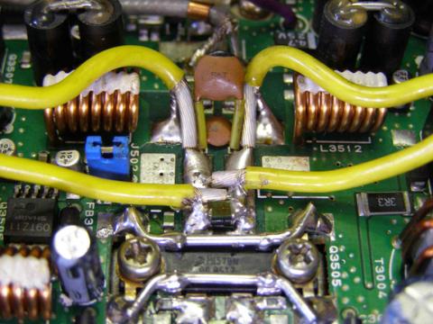
Alternately, the earlier configuration developed by Eric VK2VE, shown in Figure 6, highlights how the module's top 2 and bottom 2 connections are bent back across the top of the module and soldered to the earths on the PCB. I believe the using the solder lug approach shown in Figure 5 is superior due to the lower impedance path created, however Eric's solution reportedly works perfectly as well.
The input and output module legs can now be soldered to the pcb. With the output module fitted, the output matching capacitors (new or reused) can now be mounted and soldered across the output of the PA module.
When completed, take some time to check all the new solder joints. It's highly recommended to use some Isopropanol or Shellite and a cotton bud to clean up the area and remove all traces of solder resin.
Hopefully, all being OK, you should be able to power on the radio and now set the output power levels somewhere to the original radio specifications.
Please be warned! The new PA module is capable of supplying more output power than the original, so if you exceed the designed power output level you will be stressing the components and risk the chance of a failure of the output filter stage, which would result in costly repairs.
Set the transmit frequency to 146 MHz, and transmit and monitor the RF output and the input current to the radio.
To set the RF output levels, alter the hidden menu F35 level value combined with F22 level value to obtain the correct output power. Be careful not to exceed around 12.5 to 13 amps on Tx. This should equate to approximately 50 Watts output.
The trick in this procedure is to ensure the Tx IF gain drive (F35) is not over driving the main amplifier stage. Increase the IF Tx gain until compression starts to occur, (ie the output level change is not linear with the input level change), and then back it off a small amount. Then go ahead and set the final output level to 50 W using the F22 setting and then set F21 to 20W output.
Follow the same technique on the 430 MHz band using F36 and F33 this time, setting the maximum output to around 20W.
Now that the module has been replaced and power levels set, you are ready to perform functional tests. If you have access to a spectrum analyser, check the output for purity and harmonics.
I am investigating whether any changes to the biasing of the new module are required. To date it appears that the original configuration is suitable, however further furnctional testing will confirm that.
Also, I have added some links below that are worth a good read before you tackle the replacement of the PA module.
There has been some great work and different approaches taken by others in this area and there are many other good web sites worth a look at.
I have had great success in replacing my final using this technique and I hope you do as well.
By Scott Stewart VK3CSS
References:
http://www.freescale.com/webapp/sps/site/prod_summary.jsp?code=MRF1570N
http://comments.gmane.org/gmane.recreation.radio.hardware.yaesu.ft100/12773
http://k0lee.com/ft100/gsettings.htm
http://www.atceramics-europe.com/Capacitors/3/multilayer-capacitors
http://au.mouser.com/American-Technical-Ceramics-ATC/Passive-Components/Capacitors/Ceramic-Capacitors/MLCCs-Multilayer-Ceramic-Capacitors/Multilayer-Ceramic-Capacitors-MLCC-SMD-SMT/_/N-bkrdv?P=1yzbxm2
Background
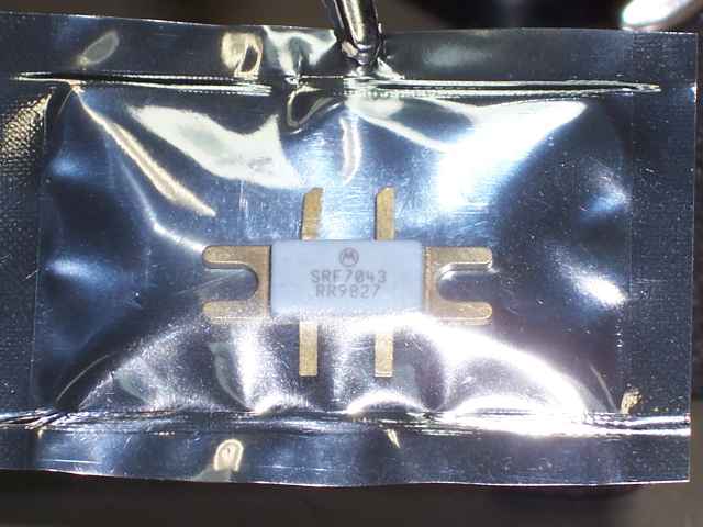
The Yaesu FT-100D is an excellent transceiver, however there is a documented issue affecting its longevity and reliability; the SRF7043 VHF/UHF Mosfet final amplifier module. Not every Yaesu FT100 seems to be affected by this issue, however in almost all cases where a module has failed, there is a noticeable physical crack in the module housing. If the crack is there and the module hasn't failed yet, it almost invariably will soon.
Because the SRF7043 VHF/UHF Hybrid RF Module is obsolete and almost impossible to obtain, many FT100D owners have reluctantly sold their transceivers, fearing that if the PA fails, the radio will become unrepairable. This has resulted in the resale price for these radios dropping below the value of comparible transceivers, even though according to many, the FT100 is a far better unit.
Some radio amateurs have tried replacing the modules with alternative types with limited success, however recently, Scott, VK3CSS, has succeeded where many have not. He has replaced his faulty SRF7043 with a MRF1570 and has restored the radio's operation to factory specification and original output power.
So far the radio has been performing perfectly and the repair appears to have been entirely successful.
New VHF/UHF finals for the FT100 Transceiver
The FT100 radios have generally been a great radio for some years now however a few are starting to show their age, with a few bad solder joints and final RF power amplifier failures. This article describes how I fitted a replacement, non-original, final VHF/UHF power amplifier module to my FT100.
I have used as much information that I could find on the web, including some great input from people like Bob Curry KC3VO and others, and to those people, I thank you.
If you have decided to tackle this adventure please be sure you have a reasonable electronic and mechanical aptitude or you may well destroy pcbs and other components. A power meter, soldering iron, a small grinding tool such as a Dremel or similar and some basic hand tools will be required to complete the job.
Replacing the Yaesu FT100D SRF7043
VHF/UHF RF MOSFET Power Amplifier
VHF/UHF RF MOSFET Power Amplifier

Search

This modification is offered as a all care, no responsibility mod. People wishing to modify their FT100 transceiver do so at their own risk.
This modification is not complex, however it does require a certain level of technical competence. If you are not experienced in repairing or servicing complex radio equipment, then you will need to enlist the assistance of someone who is, in order to perform this upgrade.
The FT100 uses extremely small surface mounted components, some of which will be prone to damage in high static fields. It is important to follow safe ESD practices and ensure that you are working in a fully static safe environment. It is also difficult to access some of the solder points and unless you are confident in your soldering ability, I would recommend that you do not attempt this on your own.
Whilst these modifications have been successfully performed without incident, I cannot be held responsible if you choose to go ahead with the modification and it does not work out for you, or you damage your radio in the process. This information is provided as-is. If you choose to use this information, then the risk is entirely yours.
Good luck, hope to hear you on the air soon.
73s and regards
Ben
VK3KBC
Disclaimer
By Scott Stewart VK3CSS
Saturday, 24th May, 2014 01:40
Figure 1
Upon opening the radio, as per figure 1, a close inspection discovered a fine crack could be seen in the ceramic cover on the final output module. The radio was still providing some output on 144 MHz but only a couple of watts on 440 MHz.
As most people are aware by now, the original VHF/UHF output module has not been available for many years, so if you own one hide it and don't tell a soul. However, there is a replacement that can be used; albeit not a direct replacement and some minor mods need to be performed on the output module, its mounting and wiring.
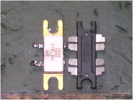
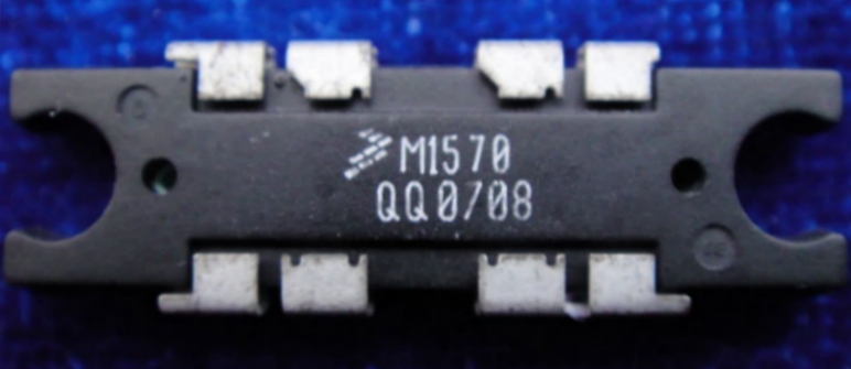
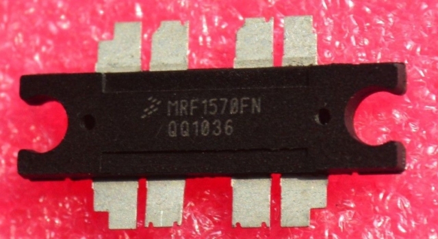
The replacement module is a Motorola MRF1570 (marked as M1570). There are 2 versions available and I chose the MRF1570FNT1 variant because it has legs. You should be able to pick one of these up for around $20 each. (See figure 2)
Now, before we go any further, you will be required to write down the current settings of the hidden functions for your FT100 radio. These hidden function levels are adjustable and are different for each radio, although Yaesu do provide a global setting that can be used.
Figure 2: Original PA and new PA
Please note that these hidden functions are additional to the normal 66 user functions that are readily accessed, such as mic gain, processor level, noise blanker level etc.
To enter the hidden functions menu, 'Power On' the radio whilst pressing buttons A B and C at the same time, then release the keys and press the FUNC key for 0.5 seconds. This should take you into edit mode and the radio will then display the first normal 66 user functions, followed by the hidden functions.
At this stage it is important not to change any of the function values, but to simply record them. The frequency step select control knob will step you through the functions and the VFO knob will allow you to change their respective values.
Next, navigate to the normal user function area and go to item #23 and then #24 (power output setting on 144 MHz and 430 MHz) and ensure the outputs are set to 100%.
Then head further down the user function list until you find the hidden functions indicated as 'F# #'. Find F21, F22 and F23 and reduce these settings to around half of the values indicated; these are the 144 MHz 20W, 144 MHz 50W and the 430 MHz 20W output settings respectively. F35 and F36 (144 MHz TX IF gain and 430 TX IF gain) also need to be reduced to around half of the values indicated.
Reducing these values will help ensure that a safety margin exists upon switching on the radio with the new PA module installed as excessive gain could result in unwanted oscillation. We will revisit these settings later to review and reset their values.
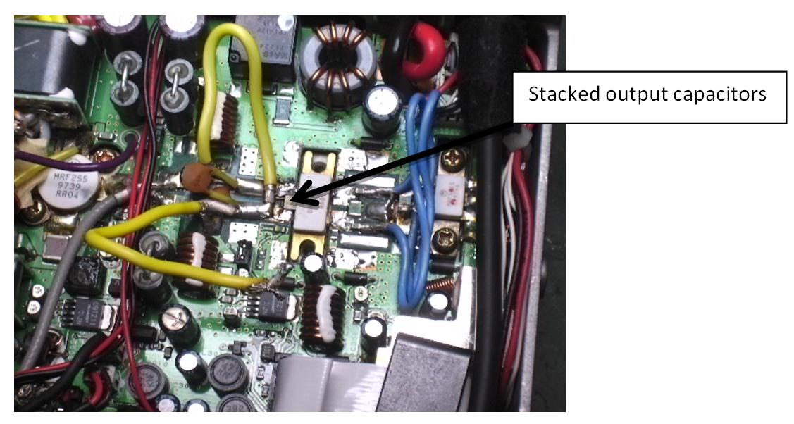
With the radio disconnected from antennas and power, the old PA module can now be removed. However, before you actually extract the module, there is a set of stacked surface mount capacitors soldered directly across the module output leads which need to be removed. (Refer to figure 3)
After removing these first, remove the module by undoing the mounting screws and desoldering the screw soldering tags, along with the 2 input and 2 output connections of the PA module. When removed, have a look to see if any white ZnO thermal conductive paste remains on the module or heat sink. In my case, there was no trace of any thermal conducting paste visible and I suspect that this may have been responsible for the failure of my PA module, and possibly many others.
Please note that these hidden functions are additional to the normal 66 user functions that are readily accessed, such as mic gain, processor level, noise blanker level etc.
To enter the hidden functions menu, 'Power On' the radio whilst pressing buttons A B and C at the same time, then release the keys and press the FUNC key for 0.5 seconds. This should take you into edit mode and the radio will then display the first normal 66 user functions, followed by the hidden functions.
At this stage it is important not to change any of the function values, but to simply record them. The frequency step select control knob will step you through the functions and the VFO knob will allow you to change their respective values.
Next, navigate to the normal user function area and go to item #23 and then #24 (power output setting on 144 MHz and 430 MHz) and ensure the outputs are set to 100%.
Then head further down the user function list until you find the hidden functions indicated as 'F# #'. Find F21, F22 and F23 and reduce these settings to around half of the values indicated; these are the 144 MHz 20W, 144 MHz 50W and the 430 MHz 20W output settings respectively. F35 and F36 (144 MHz TX IF gain and 430 TX IF gain) also need to be reduced to around half of the values indicated.
Reducing these values will help ensure that a safety margin exists upon switching on the radio with the new PA module installed as excessive gain could result in unwanted oscillation. We will revisit these settings later to review and reset their values.
With the radio disconnected from antennas and power, the old PA module can now be removed. However, before you actually extract the module, there is a set of stacked surface mount capacitors soldered directly across the module output leads which need to be removed. (Refer to figure 3)
After removing these first, remove the module by undoing the mounting screws and desoldering the screw soldering tags, along with the 2 input and 2 output connections of the PA module. When removed, have a look to see if any white ZnO thermal conductive paste remains on the module or heat sink. In my case, there was no trace of any thermal conducting paste visible and I suspect that this may have been responsible for the failure of my PA module, and possibly many others.
Figure 3
The stack of surface mount capacitors on the modules output consist of a 12, 22 and 39 pF all in parallel. Its your choice if you wish to reuse the removed capacitors or replace them with new ones. I strongly suggest that you replace them with new high quality RF capacitors such as the ATC multilayer ceramics. Capacitor technology has come a long way in the last 10 to 15 years. I initally reused the original caps (which all tested ok), only to find them fail within minutes of use after installing a new PA, which resulted in the new PA module being destroyed. Refer to the link for replacement ATC RF capacitors.
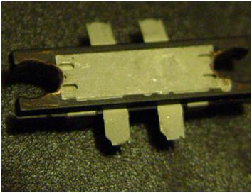
Before a new PA module can be fitted, it must be modified by elongating the mounting holes at each end to enable it to fit to the existing heat sink. I used a small grinding tip in a Dremel type tool, and with care, achieved a good result. (Refer to figure 4).
The new PA module will fit nicely in the pcb cut-out providing the 8 legs of the module are bent firmly in an upward direction to ensure the module legs are clear of the pcb cut-out.
The stack of surface mount capacitors on the modules output consist of a 12, 22 and 39 pF all in parallel. Its your choice if you wish to reuse the removed capacitors or replace them with new ones. I strongly suggest that you replace them with new high quality RF capacitors such as the ATC multilayer ceramics. Capacitor technology has come a long way in the last 10 to 15 years. I initally reused the original caps (which all tested ok), only to find them fail within minutes of use after installing a new PA, which resulted in the new PA module being destroyed. Refer to the link for replacement ATC RF capacitors.
Before a new PA module can be fitted, it must be modified by elongating the mounting holes at each end to enable it to fit to the existing heat sink. I used a small grinding tip in a Dremel type tool, and with care, achieved a good result. (Refer to figure 4).
The new PA module will fit nicely in the pcb cut-out providing the 8 legs of the module are bent firmly in an upward direction to ensure the module legs are clear of the pcb cut-out.
Figure 4: Elongation of mounting holes
With the module prepared, you are now ready to fit the PA module. Ensure you coat the base of the module with adequate thermal paste, orient the module correctly, then apply the mounting screws and tighten lightly. Ensure the module is positioned in the centre of the pcb cut-out with a small clearance between the module and the pcb.
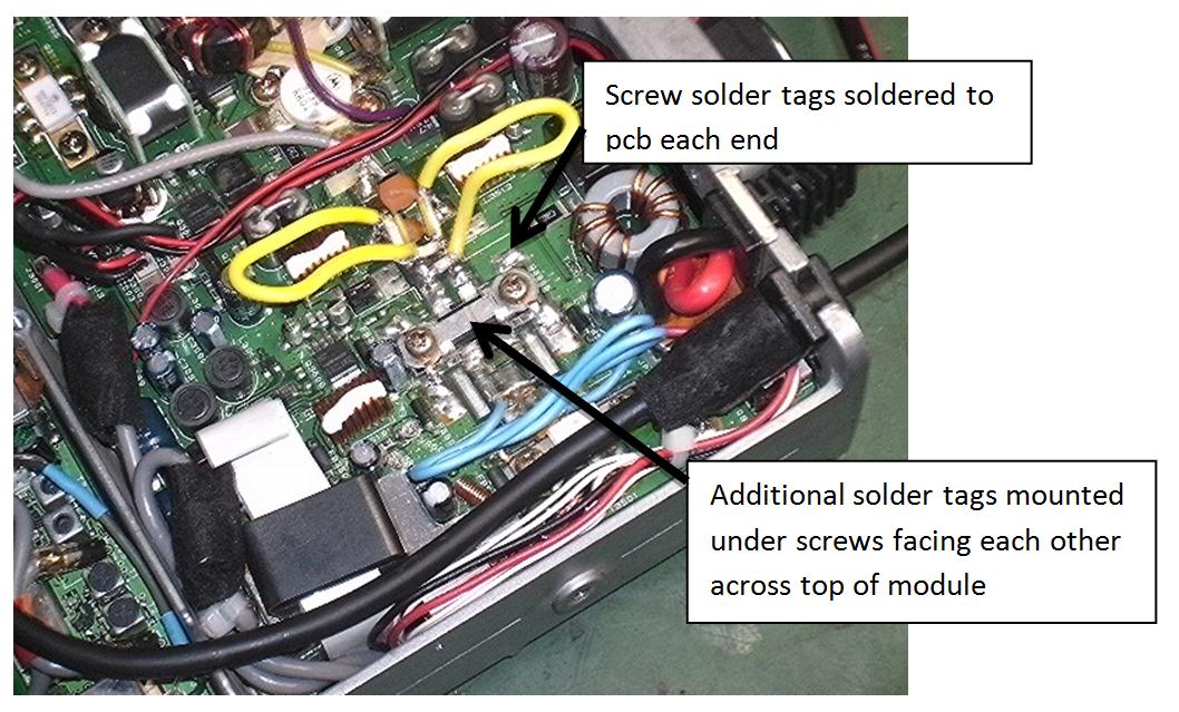
Now remove the mounting screws, one at a time, and fit the earthing washer and a solder tag between the module and the screw head and re-tighten. Ensure the solder earthing washers and the added solder tags are located in the correct position for soldering during the tightening. (Refer to figure 5).
With the module prepared, you are now ready to fit the PA module. Ensure you coat the base of the module with adequate thermal paste, orient the module correctly, then apply the mounting screws and tighten lightly. Ensure the module is positioned in the centre of the pcb cut-out with a small clearance between the module and the pcb.
Now remove the mounting screws, one at a time, and fit the earthing washer and a solder tag between the module and the screw head and re-tighten. Ensure the solder earthing washers and the added solder tags are located in the correct position for soldering during the tightening. (Refer to figure 5).
Figure 5: Solder Tag Earth Strip
The module's top 2 and bottom 2 connections should now be bent back across the top of the module and soldered to the solder tags lying on top of the PA module. The screw earthing tags should also be soldered to the pcb.
The module's top 2 and bottom 2 connections should now be bent back across the top of the module and soldered to the solder tags lying on top of the PA module. The screw earthing tags should also be soldered to the pcb.