
PIC-A-Star Links
http://members.inode.at/harald.gosch/Projects/Pic_a_Star/body_pic_a_star.html
http://www.qsl.net/on4mj/dsp.html
http://www.carnut.info/singleboard/singlestar.htm
http://www.g4nvh.net/
http://carnut.info/star-parts/builders-pics/leslie-france/les_GW3PEX.htm
http://members.inode.at/harald.gosch/Projects/Pic_a_Star/BLOG/blog.html
http://www.homebrew-radios.net/trxavr_picastar/trxavr_picastar.htm
http://www.g3vpx.net/picastar/box.htm
http://www.carnut.info/star-parts/
Wednesday, 2 July 2009 00:12
Background
The Pic-A-Star is an advanced, homebrew DSP based HF Transceiver designed by Peter Rhodes, G3XJP.
The transceiver is designed to operate between 160m and 10m on LSB, USB and CW only.
The radio compares extremely well with commercial high end Amateur Radio HF transceivers and in many cases, outperforms them.
The Pic-A-Star is a complex transceiver to build, however there are many in operation today and there are numerous Web Sites detailing construction techniques with tips and hints on building your own. The unit can be widely customised to suit each individual's requirements or parts availability.


TO BE CONTINUED...
The next step is to join the http://groups.yahoo.com/group/picastar-users/ Yahoo Group.
This group was formed as a replacement forum to discuss the construction and use of the Picastar HF band transceiver which was designed and developed by Peter, G3XJP. (Peter's original picastar group closed on 1st Sept 2008)
Once your memberships are approved, make sure you download and read the original articles by Peter and then download all of the updates and subsequent articles and documentation.
I also found that Glenn (VK3PE) has an extremely detailed web site covering the building of PICASTAR's in VK and around the world at http://www.carnut.info/star-parts/glennpcbs.htm. Glenn has produced some printed circuit boards for the PICASTAR and I was fortunate enough to get hold of some, so this will make the construction of the radio a bit easier in my case.
•
The original articles
•
All the modification data
•
All the software
•
Configuration and operating instructions
•
Links to other related sites

Over the past 18 months I have been following the progress of friend, Gerald VK3GJM, as he's built two Pic-A-Star's and I'm impressed with their performance.
Consequently, I've decided to build my own Pic-A-Star as time permits. I've decided to document the process in order to assist others contemplating doing the same but who are not quite sure where to start or what's involved.
First Steps
The first step to take if you decide to build this transceiver is to join the 'PICAPROJECT' Yahoo User Group at http://uk.groups.yahoo.com/group/picaproject/. This group will allow you to assess the full scope of the project (which is clearly not for beginners).
The 'PICAPROJECT' Yahoo Users Group publishes the following:
What's next?
When you read through the documentation, you'll realise that there is a wealth of information to process. Gerald recommended that I print the material out in colour and put together a binder for the project. That was good advice; put together a binder with all of the information you'll need. Keep in mind that this project is not a kit. You won't find all of the information that you'll need in one place and you won't be able to buy all of the required parts from one supplier.
The original Bill of Materials (parts list) was compiled by Glenn and I modified the spreadsheet to utilise Excel's Pivot Tables feature in order to sort out parts so that I could easily obtain totals of all of the required components by type. I've attached that spreadsheet in case it's of use to others. This parts list pertains to Glenn's boards so it may be slightly different if you're going by the original design articles. BOM_Ben_20100527.xlsm
Locating the Parts
The PIC-A-Star doesn't use common components. You're not going to build it using BC548's out of the junk box. There are some difficult to obtain components, but none are impossible to get hold of at the time of writing this article.
A small number of parts are no longer available in one off quantities and you may have to buy some in small lots. The only supplier I could find for the audio amplifier IC would only sell them in lots of 5. Some components, like the rotary encoder assembly, you'll have to construct from scratch or recycle a piece of commercial hardware.
I found that I was able to obtain most of the needed semiconductors and passive components from RS, Farnell and Futurelec. Some RF transistors came from RF Spares in the US. The Parts List above has a supplier field which indicates where I obtained the components from. Keep an eye out on eBay also for the components if you're not in a hurry, as they do surface from time to time and are often cheaper than you'll get elsewhere.
The ADSP-2181, which is probably the most expensive component, has been advertised on eBay at nearly half of the retail price.
I didn't have a good supply of new surface mount components so I bought a bulk assortment of SMD resistors and capacitors on eBay and then topped up the collection with the most used values such as (tba). I chose to use 1206 components but you can also use the smaller 0805 parts. Most of the IC's are SOIC SMD packages.
What You will Need in the Workshop
Apart from the normal electronics workshop tools, the PIC-A-Star build can do with a few additional items if you don't already have them. You won't need a SMD rework station. A conventional fine tipped, temperature controlled soldering station will be fine.
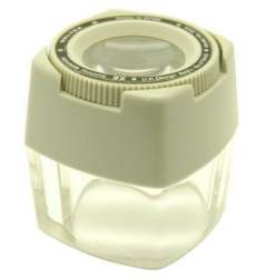
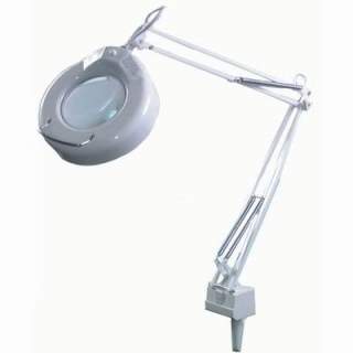
Because there are a lot of surface mounted components to work with, you'll need a decent magnifier to work with the small components and in particular to check the printed circuits for shorts.
Good visibility and a magnified desk lamp helps a lot and when combined with a 10x or 15x loupe and the combination works well for real closeups. These two items were found on eBay.
Apart from the normal electronics workshop tools, the PIC-A-Star build can do with a few additional items if you don't already have them. You won't need a SMD rework station. A conventional fine tipped, temperature controlled soldering station will be fine.
Because there are a lot of surface mounted components to work with, you'll need a decent magnifier to work with the small components and in particular to check the printed circuits for shorts.
Good visibility and a magnified desk lamp helps a lot and when combined with a 10x or 15x loupe and the combination works well for real closeups. These two items were found on eBay.
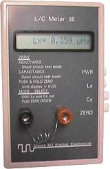
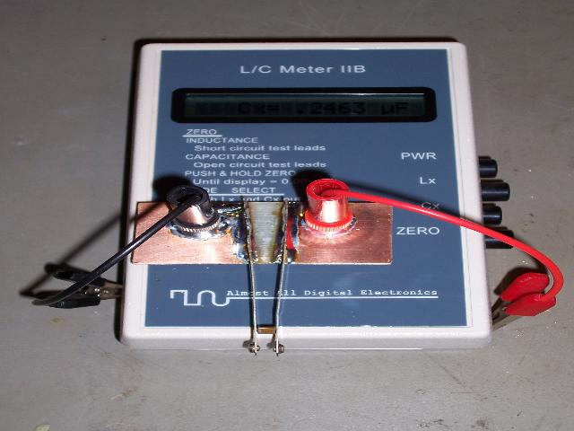
A good Inductance and Capacitance meter is essential. You will be building most of the inductors and you'll need to check every component before soldering it onto your PCB and there'll be quite a few to check. You want something that is fast, accurate and almost handsfree. I use AADE's L/C Meter IIB from http://www.aade.com/lcmeter.htm.
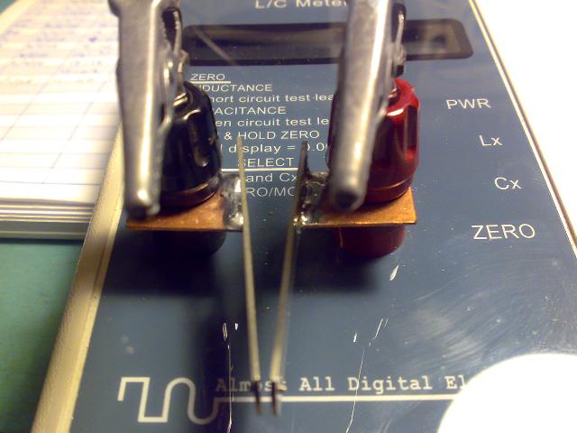
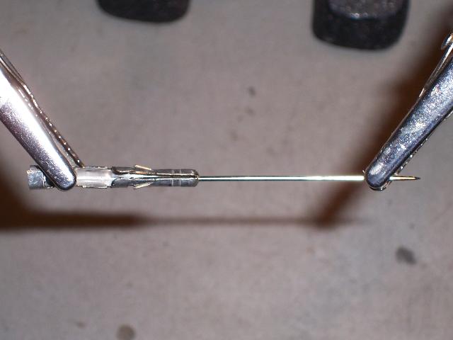
A test jig will also speed up component testing. An example made by Gerald, VK3GJM, from a set of old relay contacts is shown below: Using insulated tweezers, slide the component between the two contacts to get a reading. The light spring tension will also hold the component in place without the tweezers.
You'll also find that normal multimeter probes are pretty much useless for testing SMD components. Adriaan, VK3NL told me about how he made up some probe adapters using utilux plug inserts and sewing needles so I thought that I'd give that a try. Some amateurs use needles poked through corks as probes and apparently that works too.
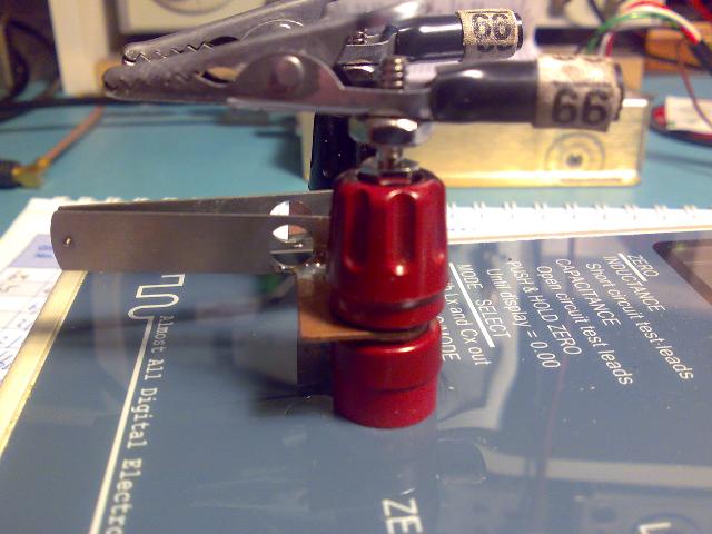
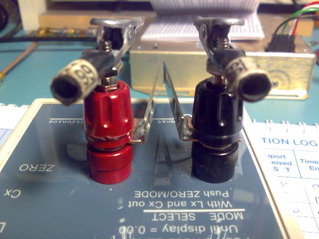
My version, based on Gerald's design, is made out of double sided PCB material.
I cut the copper on both sides to form a gap and peeled the copper off the top and bottom after heating it with a soldering iron tip to melt the glue.
I then re-used the copper to connect the top and bottom copper surfaces (just behind the banana terminals) on both sides to provide a better contact area for the banana terminals.
Holes drilled in the PCB align with the banana terminals and the board is simply tightened down.
The relay contacts soldered easily to the PCB copper and were be slightly bent to set the required tension.
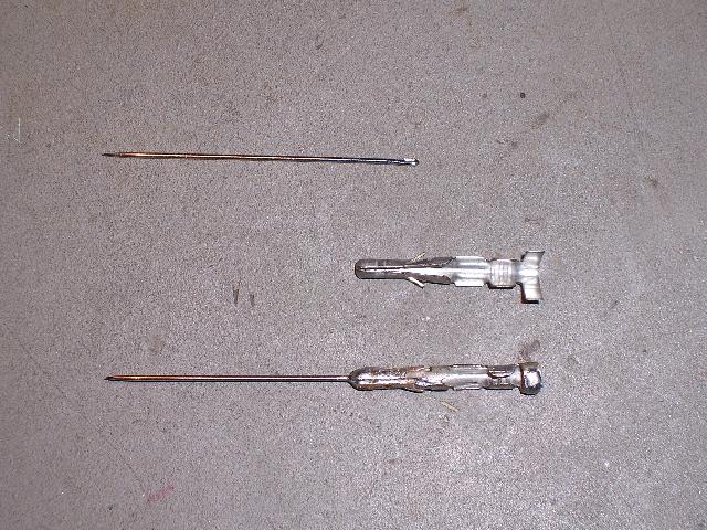
The utilux inserts are just the right size to allow a fluke multimeter probe tip to press tightly into the back. There is also a convenient hole in the front to mount a sewing needle through. Once the needle is in place, the connector is soldered to hold everything in place.
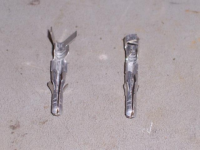
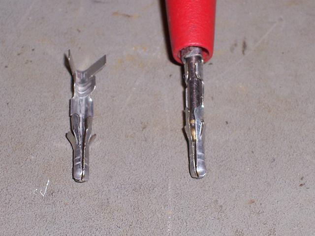
You may need to give the assembly a squeeze with a pair of pliers just to tighten the fit a bit more but I found that there was almost no movement once I pluged my multimeter probes into the back of these connectors.
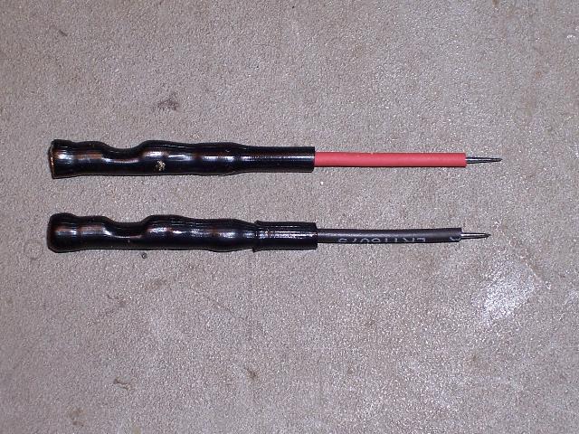
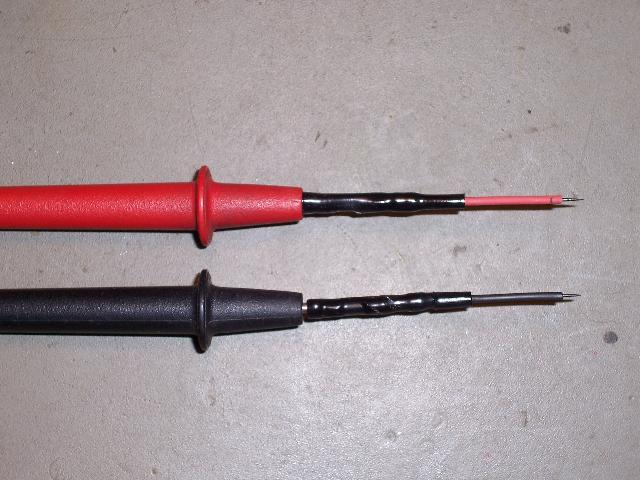
Finally, heatshrink is placed over the extended tips to insulate them. In hindsight, the tips could even have had a little more heatshrink at the needle tip because SMD device pins are pretty close together and one slip could accidently cause a short. A simple twist and pull easily removes the extended tips.
Yeah I know what you're thinking ... I ran out of red heatshrink!
Yeah I know what you're thinking ... I ran out of red heatshrink!
Printed Circuit Boards
If you're keen, you can make the printed circuit boards yourself. All of the files are available in the document repository and many Picastar builders have made excellent PCB's using the Laser Printer and Iron transfer method.
I took advantage of a group purchase of PCB's created by Glen, VK3PE. These boards were professionally manufactured and very reasonably priced, so that saved me a bit of effort. Glen is currently experimenting with a single board PCB design (http://www.carnut.info/singleboard/Ver_B/singlestar_B.htm) and it may be worth doing a Google search and checking the forums to see if there is anyone is facilitating commercially made Picastar PCB's.
Decision Time
After organising the PCB's, I started looking at collecting the rest of the components that I needed. A few years ago this may have been easier because the PICASTAR Project hadn't deviated much from Peter's original design, but over the past few years there have been various enhancements. It was time to consider what was out there and choose how to move forward with my design.
The first thing I did was surf the Web looking for any information relating to variations. Again, Glen's site, http://www.carnut.info/star-parts/glennpcbs.htm was a wealth of historical information.
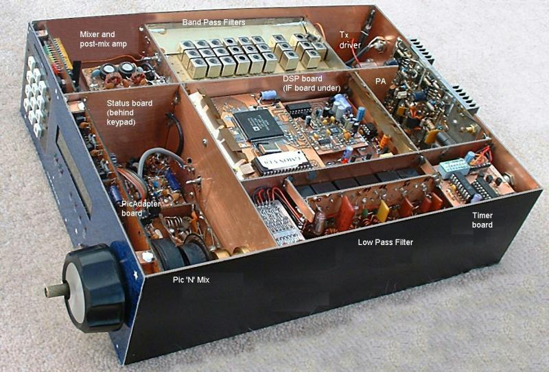
Fundamentally the PICaSTAR is a full DSP based Multi band HF transceiver build around a PIC 'N MIX DDS Synthesiser designed by Peter Rhodes, BSc, G3XJP. Peter's design is based on a number of functional PCB modules all wired together.
The beauty of Peter's design is that it is flexible in that it allows the builder to customise the radio configuration to suit themselves, and this explains why there is no Picastar 'kit'.
Unfortunately one ramification of this flexibility is that you have to read the original articles and new material to decide what you wish to incorporate into your design. Only once you've done that will you be able to generate the bill of materials for the parts that you will need.
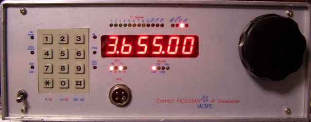
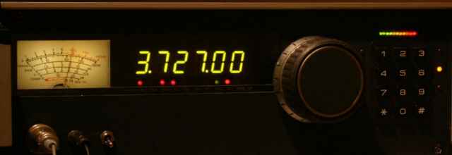
Deciding whether to build the original LED based design or to use one of the new graphical display options is a significant consideration.
After organising the PCB's, I started looking at collecting the rest of the components that I needed. A few years ago this may have been easier because the PICASTAR Project hadn't deviated much from Peter's original design, but over the past few years there have been various enhancements. It was time to consider what was out there and choose how to move forward with my design.
The first thing I did was surf the Web looking for any information relating to variations. Again, Glen's site, http://www.carnut.info/star-parts/glennpcbs.htm was a wealth of historical information.
Fundamentally the PICaSTAR is a full DSP based Multi band HF transceiver build around a PIC 'N MIX DDS Synthesiser designed by Peter Rhodes, BSc, G3XJP. Peter's design is based on a number of functional PCB modules all wired together.
The beauty of Peter's design is that it is flexible in that it allows the builder to customise the radio configuration to suit themselves, and this explains why there is no Picastar 'kit'.
Unfortunately one ramification of this flexibility is that you have to read the original articles and new material to decide what you wish to incorporate into your design. Only once you've done that will you be able to generate the bill of materials for the parts that you will need.
Deciding whether to build the original LED based design or to use one of the new graphical display options is a significant consideration.
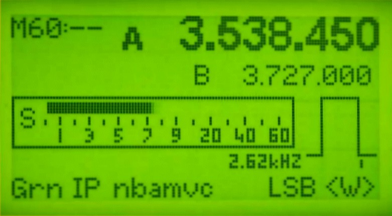
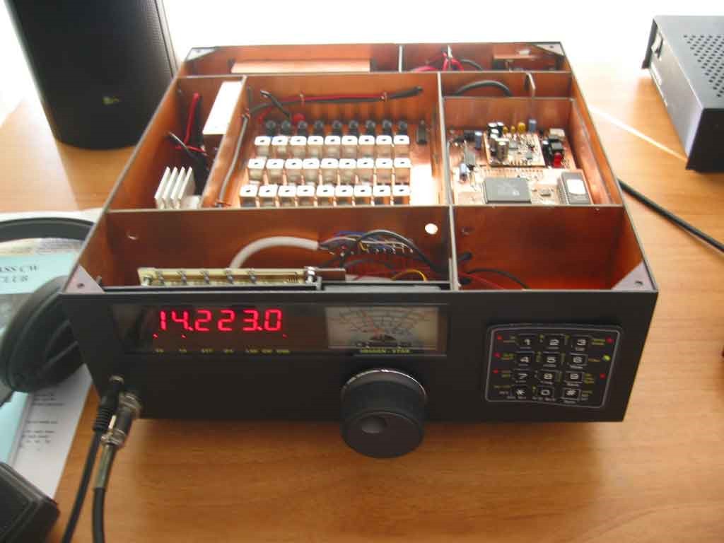
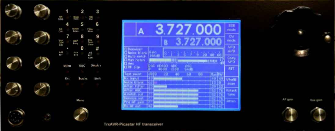
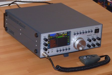
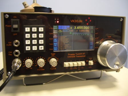
Whilst the original Picastar used the PIC 'n MIX board to generate the frequency synthesis and provided a digital readout, a subsequent design has emerged called the TrxAVR Picastar.
An excellent site on this design can be found at : http://www.homebrew-radios.net/trxavr_picastar/trxavr_picastar.htm.
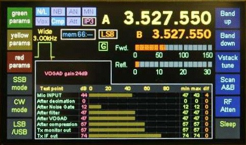
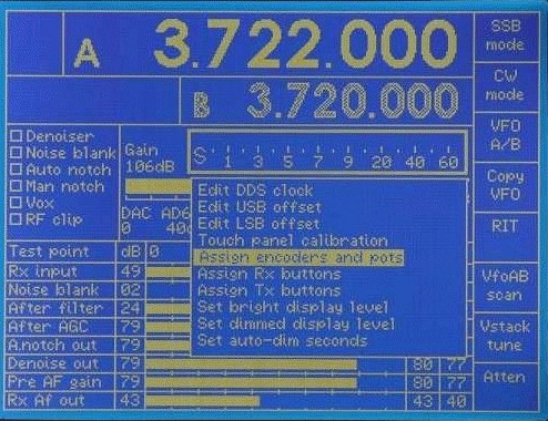
The TrxAVR-Picastar is still based on the excellent work of Peter, G3XJP, whilst also incorporating an alternative controller and user interface for the Picastar Transceiver based on a graphical display and touchscreen option.
An excellent site on this design can be found at : http://www.homebrew-radios.net/trxavr_picastar/trxavr_picastar.htm.
The TrxAVR-Picastar is still based on the excellent work of Peter, G3XJP, whilst also incorporating an alternative controller and user interface for the Picastar Transceiver based on a graphical display and touchscreen option.


PICASTAR DSP Transceiver Project

Search
