
FEI 5650A Rubidium Frequency Standard
The FEI 5650A Internal Adjustment by Gerald Molenkamp VK3GJM
Some time back, we lost power to the house for 3-4 hours. Although the standard is connected to the mains via an extremely low noise 15V power supply and battery back-up UPS, ultimately there is only so much a UPS can keep the 5650A running in conjunction with my distribution amp consuming just below 1 amp.
Once power was restored, the unit failed to lock. Thinking it needed more time to restore heat back into the physics package after a 3-4 hour outage, the unit never locked after letting it settle overnight. I decided to investigate the reason.
The following step is an easy indicator why this fix was initiated - I decided to connect a counter with an accurate reference to the 10Mhz output. I quickly realised the unit in my case was sweeping between 9.99986 and 9.99959MHz +/-. Naturally, the first thing that came to my mind was, it will never lock if the sweep circuitry only covers a window below 10MHz.
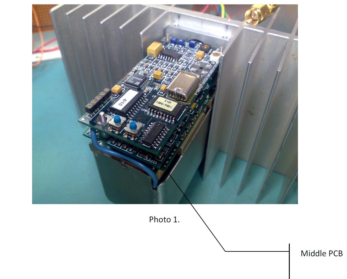
The sweep circuit controls the 50.225MHz oscillator which is located on the middle PCB; see photo 1 below. The crystal body has a small heater. The circuitry also has a fine adjustment trimmer C245. Adjustment of the trimmer got the upper
sweep to 9.99997MHz. Unfortunately this is where it stopped dead. No matter which position I adjusted C245 to, the sweep window would not exceed 9.99997MHz
Some time back, we lost power to the house for 3-4 hours. Although the standard is connected to the mains via an extremely low noise 15V power supply and battery back-up UPS, ultimately there is only so much a UPS can keep the 5650A running in conjunction with my distribution amp consuming just below 1 amp.
Once power was restored, the unit failed to lock. Thinking it needed more time to restore heat back into the physics package after a 3-4 hour outage, the unit never locked after letting it settle overnight. I decided to investigate the reason.
The following step is an easy indicator why this fix was initiated - I decided to connect a counter with an accurate reference to the 10Mhz output. I quickly realised the unit in my case was sweeping between 9.99986 and 9.99959MHz +/-. Naturally, the first thing that came to my mind was, it will never lock if the sweep circuitry only covers a window below 10MHz.
The sweep circuit controls the 50.225MHz oscillator which is located on the middle PCB; see photo 1 below. The crystal body has a small heater. The circuitry also has a fine adjustment trimmer C245. Adjustment of the trimmer got the upper
sweep to 9.99997MHz. Unfortunately this is where it stopped dead. No matter which position I adjusted C245 to, the sweep window would not exceed 9.99997MHz
Good luck.
73s Gerald VK3GJM
73s Gerald VK3GJM
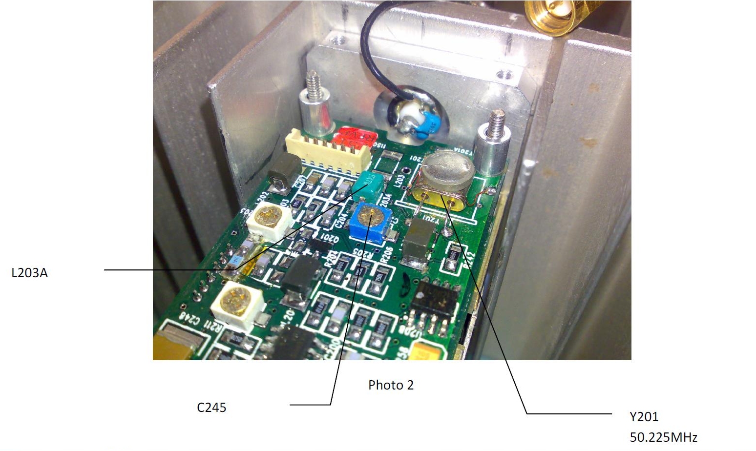
After tracing out several parts around the crystal, I decided to replace L203A. Removing this SMD inductor, it read 514nH? on my inductance meter. The obvious choice was to lower the value, so I replaced it with a 470nH stamped device, but the actual value was around 413nH.
I am pleased to report the revised value pulled Y201 closer to 10MHz and C245 allowed me to provide some adjustment with a window +/- a few hundred Hz. Once assembled the sweep during warmup is now from 9.99987 to 10,0004MHz, which was sufficient to lock after the physics package came up to temperature.
Photo2 below illustrates and points to C245, L203A and the Y201 50.225MHz XTAL on the middle PCB.

Friday 10th Sept 2010, 23:20

Search
